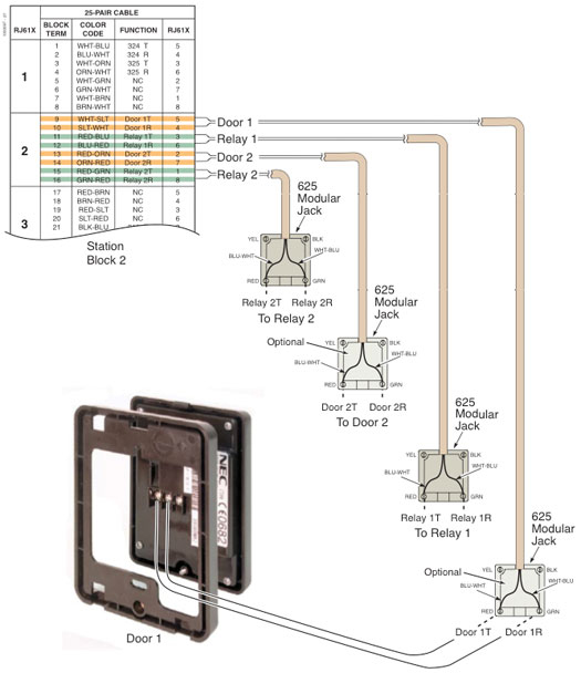
Setting up Built-In Door Ports on DSX-40
1. Connect an Analog Door Box to a DSX-40 Door Box Port.
- DOOR 1 is DSX-40 extension 326.
- DOOR 2 is DSX-40 extension 327.
-
Use the following illustration as a guide when connecting Analog Door Boxes to DSX-40.

- Refer to the DSX-40 Hardware Manual for additional connection details.
2. Have a "built-in" Door Box activate a control relay.
-
This programming does not apply to a Door Box connected to a 2PGDAD Module.
-
2101-06: Door Relay Assignment [Stations: Config: Setup: Type (2101): Door Relay Assignment]
For DOOR 1 (326) or DOOR 2 (327), assign the associated control relay. - 1 for relay CPU #1 (normally assigned to DOOR 1/extension 326).
- 2 for relay CPU #2 (normally assigned to DOOR 2/extension 327).
Option Description 0 [Default] Not assigned. 1 CPU Relay 1 (DSX40-1) 2 CPU Relay 2 (DSX40-2) -
1605-03: Door Relay Unlock Timer [System: Timers: Features: Control (1605): Door Relay]
This timer sets the interval that the system or PGDAD Module relay remains closed after a keyset user activates (closes) the relay. After this interval, the relay automatically returns to its open (idle) state. Option Description 0 Disabled. 1-9999 Seconds. [Default] = 30 seconds.
3. To have a Door Box operate a DSX-40 and PGDAD relay in tandem:
-
2101-06: Door Relay Assignment [Stations: Config: Setup: Type (2101): Door Relay Assignment]
For the 2PGDAD Module Door Box extension number, assign the same associated control relay that is assigned to the built-in Door Box port. Option Description 0 [Default] Not assigned. 1 CPU Relay 1 (DSX40-1) 2 CPU Relay 2 (DSX40-2) - Both relays will now operate simultaneously.