PGDAD Module Door Box and Relay Connections

Understanding the 2PGDAD Module Connecting Blocks

You need to remove 2PGDAD Module Cover to see the connecting blocks, and you'll need to remove the cable knockout before wiring.

To remove the 2PGDAD Module Cover
  • Follow the instructions in your system's Hardware Manual.
To remove the 2PGDAD Module Cable Knockout:
  • Follow the instructions in your system's Hardware Manual.
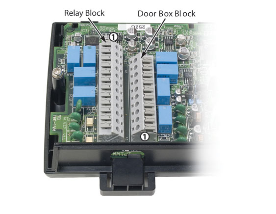
With the cover removed and the 2PGDAD Module Cable Knockout facing you, you'll see the two connecting blocks.
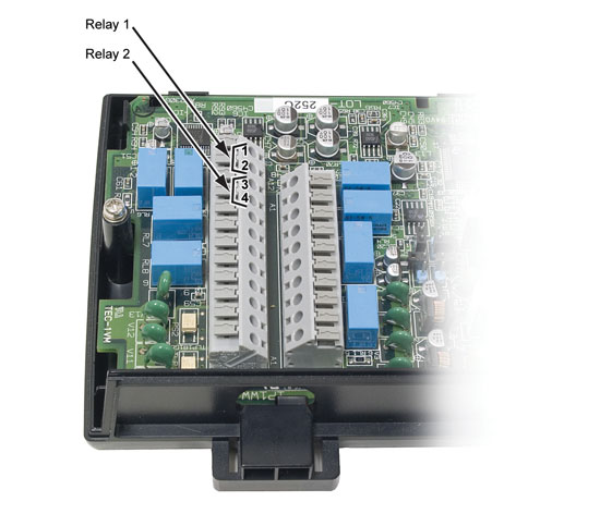
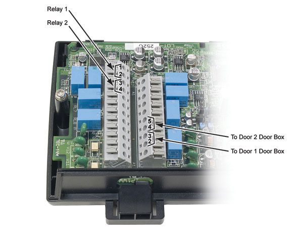
  • The block on the left is the Relay Block. Use this block for connecting Page and Door Box Relays. The circuits used by the system are at the top of the block. Pin 1 is the first pin at the top.
  • The block on the right is the Door Box block. It provides connection for the two Analog Door Box circuits. The circuits used by the system are at the bottom of this block, and pin 1 is the last pin on the bottom.


Wiring the Connecting Blocks

Analog Door Box Wiring


  1. Position the 2PGDAD Module so the cable knockout is facing towards you. The Door Box block is on the right.
  2. Door Box 1 uses pins 2 and 3 at the bottom of the block.
    • Be sure to skip pin 1.
  3. Door Box 2 uses pins 4 and 5.
    • Always refer to your system's Hardware Manual for additional details.

The following illustration shows how you can use a small, flat-blade screwdriver to help you seat the wires in the blocks.


Relay Wiring

Be sure the device you connect to the 2PGDAD Module Relays is compatible with the following specifications.

2PGDAD Module Relay Contact Specifications
Contact Configuration: Normally open
Maximum Load: 500 mA @ 24 VDC, 250 mA @ 120 VAC


  1. Position the 2PGDAD Module so the cable knockout is facing towards you. The Relay Block is on the left.
  2. Pins 1 and 2 are for Relay 1.
    • f you dial the extension number for Analog Door Box 1 and press [Open Door] [Open], Relay 1 will close.
  3. Pins 3 and 4 are for Relay 2.
    • If you dial the extension number for Analog Door Box 2 and press [Open Door] [Open], Relay 2 will close.
    • Always refer to your system's Hardware Manual for additional details.
  4. The length of time the relay remains closed is determined by the setting of 1605-03: Door Relay Unlock Timer [System: Timers: Features: Control (1605): Door Relay]. The default is 30 seconds.

The following illustration shows the completed wiring for both Analog Door Boxes with relay control.